
What is a fuel sending unit?
An aircraft fuel sending unit (also referred to as a fuel sensor, fuel sender or fuel probe) is a crucial component for measuring fuel quantity. In a modern system, the fuel sending unit employs advanced technology to accurately measure and transmit fuel level data to the cockpit instrumentation, providing pilots with vital information for flight planning and safety.

Where are fuel sending units located?

Aircraft fuel sending units are typically mounted within fuel tanks or reservoirs. They employ a variety of measurement techniques to accurately determine the fuel level. These techniques range from float-based systems to other methods, such as probe, ultrasonic and reed switch. Regardless of the specific technology used, the core principle involves translating the position of a fuel tank’s liquid level into an electrical signal that can be interpreted by the aircraft’s avionics.
An aircraft’s fuel tanks are usually in the wings. Most fuel tank construction is either metal or a rubber bladder. Rubber bladders and some rigid tanks are removable. However, most small aircraft tanks are built into the wing structure and are not removable. Learn more about types of fuel tanks here.
How does a fuel sending unit work?
There are at least three construction types of fuel sensors for aircraft: floats, probes and remote sensing. First, let’s examine float-based senders.
Float-Based Fuel Senders
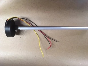
A float-based fuel sender provides information to the fuel gauges allowing the pilot to monitor the fuel level. The system typically consists of a float, electronics, wiring, and a fuel gauge. There are several technologies that make this system work. Older technologies are prone to early failure and high error due to electronics in the fuel tank. New technologies, such as magnetic resonance, keep electronics out of the fuel tank and consistently have high accuracy.

How Float-Based Sensors Work:
- Float: The float is usually made of a buoyant material like foam or plastic. It’s designed to float on the surface of the fuel inside the tank. As the fuel level changes, the float rises and falls accordingly.
- Variable Measurement: Inside the fuel tank, there is a measuring device that is connected to the float. The measurement changes based on the position of the float. This is typically achieved through a sensor as the float moves up and down.
- Electrical Circuit: The measuring device is part of an electrical circuit that includes the fuel gauge on the dashboard. As the float moves and changes the electrical signal, the digital gauge reflects this change.
- Fuel Gauge: The fuel gauge on the instrument panel displays the fuel level to the driver. It’s calibrated to show the appropriate fuel level based on the signal from the fuel sender.
- Calibration: The fuel sender system needs to be calibrated to ensure accurate readings. This calibration involves setting the range of values corresponding to various fuel levels. Manufacturers do this to ensure that the fuel gauge accurately displays the actual fuel level in the tank.
Learn More About Float-Based Systems
Are your fuel senders degraded or non-functioning?
CiES manufactures new fuel senders for nearly 700 small aircraft models. Each fuel sender is made-to-order to ensure accurate replacement for your aircraft. Fill out our quote form or order form to get started.
Probe-Based Fuel Senders
A fuel sender probe system, also known as a fuel level sensor or fuel sender unit, is another way to measure the fuel level in an airplane’s fuel tank. These systems utilize modern technologies, often employing capacitance, resistance, or ultrasonic principles.
How Probe-Based Sensors Work:
- Capacitance Principle: The capacitance-based fuel sender probe system relies on the principle of capacitance, which is the ability of a capacitor to store an electric charge between its two conductive plates separated by a dielectric material (insulator).
- Probe Configuration: The fuel sender probe system consists of two main components: the probe assembly inside the fuel tank and the control module located elsewhere in the aircraft.
- Probe Assembly: The probe assembly is a long, thin rod or strip that extends into the fuel tank. It is made of a non-conductive material, such as plastic or ceramic. The probe has a conductive material along its length, typically in the form of a wire, coating, or tracks.
- Dielectric Constant: The fuel itself acts as a dielectric material between the conductive probe and the inner walls of the fuel tank. The dielectric constant of the fuel changes based on the fuel level. When the fuel level is higher, more of the probe is immersed in fuel, resulting in a different dielectric constant compared to when the fuel level is lower.
- Capacitance Variation: The capacitance between the conductive probe and the fuel tank’s walls changes as the fuel level changes. When more of the probe is submerged in fuel, the capacitance increases. Conversely, when less of the probe is in contact with the fuel, the capacitance decreases.
- Control Module: The control module receives the varying capacitance signal from the probe assembly. It is equipped with circuitry to convert the changing capacitance values into a corresponding electrical signal, typically a voltage or frequency.
- Signal Processing: The control module processes the electrical signal to determine the fuel level. It compares the signal to a pre-calibrated table or algorithm that relates capacitance values to fuel levels. This information is then sent to the aircraft fuel gauge to alert the pilot.
Learn More About Capacitive Systems
Remote-Sensing Fuel Senders
Fuel sender ultrasonic, LiDAR (Light Detection and Ranging) or radar systems are alternate technologies used to measure the fuel level in a vehicle’s fuel tank using the principles of remote sensing. These systems offer non-contact fuel level measurements (no equipment in the tank), where float-based or capacitance-based systems might not be possible.

How Remote Sensing Technologies Work:
1. Ultrasonic System
- Ultrasonic Sensor: The heart of the system is the ultrasonic sensor located within the fuel tank. This sensor emits ultrasonic waves and receives the echoes that bounce back from the fuel surface.
- Control Module: The control module or electronic unit is responsible for processing the ultrasonic signals, calculating the fuel level, and transmitting the information to the dashboard fuel gauge.
- Ultrasonic Wave Emission: The ultrasonic sensor emits short bursts of ultrasonic waves, which are high-frequency sound waves that are not audible to humans. These waves travel at the speed of sound and propagate through the fuel inside the tank.
- Echo Reception: When the ultrasonic waves encounter the fuel surface, they are partially reflected back towards the sensor. The sensor detects these echoes and measures the time it takes for the waves to travel to the fuel surface and back.
- Distance Calculation: Using the known speed of sound in the fuel (which is affected by factors like temperature and fuel composition), the system calculates the distance between the sensor and the fuel surface based on the time-of-flight of the ultrasonic waves.
- Fuel Level Determination: As the fuel level changes, the distance between the ultrasonic sensor and the fuel surface also changes. The system continuously measures this distance and calculates the corresponding fuel level.
2. LiDAR (Light Detection and Ranging) System:
- Emission of Laser Pulses: A LiDAR system emits short bursts of laser pulses in the form of light. These laser pulses are directed towards the surface of the fuel in the tank.
- Reflection Time Measurement: The emitted laser pulses travel at the speed of light and bounce off the surface of the fuel. The LiDAR system measures the time it takes for the laser pulse to travel to the surface of the fuel and back to the sensor.
- Calculation of Distance: By knowing the speed of light and the time taken for the round trip of the laser pulse, the LiDAR system calculates the distance between the sensor and the fuel surface.
- Fuel Level Determination: As the fuel level changes, the distance between the sensor and the fuel surface also changes. The LiDAR system continuously measures this distance and calculates the fuel level in real-time.
- Output and Display: The calculated fuel level information is then processed and displayed on the aircraft gauges, allowing the pilot to monitor the fuel level.
3. Radar (Radio Detection and Ranging) System:
- Emission of Radar Waves: A radar-based fuel sender system emits radio waves instead of laser pulses. These radar waves are electromagnetic signals that travel at the speed of light.
- Reflection and Echo Time: Similar to LiDAR, the emitted radar waves bounce off the fuel surface and create echoes. The radar system measures the time it takes for the radar wave to travel to the fuel surface and return as an echo.
- Calculation of Distance: By knowing the speed of light and the time taken for the radar wave’s round trip, the radar system calculates the distance between the sensor and the fuel surface.
- Fuel Level Determination: The changing distance between the sensor and the fuel surface corresponds to changes in the fuel level. The radar system continuously measures this distance and calculates the fuel level in real-time.
- Output and Display: Similar to LiDAR, the calculated fuel level information is processed and displayed on the vehicle’s dashboard for the driver’s convenience.
Learn More About Ultrasonic/LiDAR/Radar Systems
Did you know that fuel management is the sixth leading cause of aviation accidents (NTSB)?
Few problems generate more pilot anxiety than determining how much fuel actually remains in the tanks. Without a proper fuel quantity measuring system, pilots must rely solely on manually figuring fuel calculations for every flight.
Manually figuring the amount of fuel necessary and installed before take-off isn’t foolproof. And pilots can’t make physical checks once in motion, like automobiles. At several thousand feet, proper instrumentation is crucial to determine if a fuel problem exists. This could be a problem in the fuel tanks, fuel leaks, fuel flow, or other fuel-related problems.

Furthermore, manually figuring necessary fuel for flight, without a way to monitor during flight, is a recipe for disaster. In examination of the hierarchy of controls diagram below, let’s consider fuel starvation:
Fuel Starvation Hazards
The hazard of fuel starvation is not eliminated by manually calculating fuel quantity at the beginning of flight (Level 5). The hazard can’t be substituted (replaced) by manually calculating your necessary fuel either (Level 4). Neither can manual calculations employ engineered controls to isolate pilots and passengers from this hazard (Level 3). By manually figuring fuel, a pilot has only changed the way they work. It’s an administrative action (Level 2). In other words, this simple action sits at the level right before failure (Level 1).
If you want to eliminate the hazard of fuel starvation (Level 5) and engage the most effective Hierarchy of Controls, you must physically remove the hazard. This means ensuring current fuel measurement is accurate and reliable or upgrading the parts measuring fuel quantity in your aircraft – the fuel sending units.
What are the technologies powering fuel sending units?
Fuel sending units employ various technologies to measure and transmit fuel level information to the aircraft’s fuel gauge. Some of the common technologies powering fuel sending units include resistive, capacitive, ultrasonic, radar, LiDAR, reed switch and magneto-resistive systems.
Resistive System
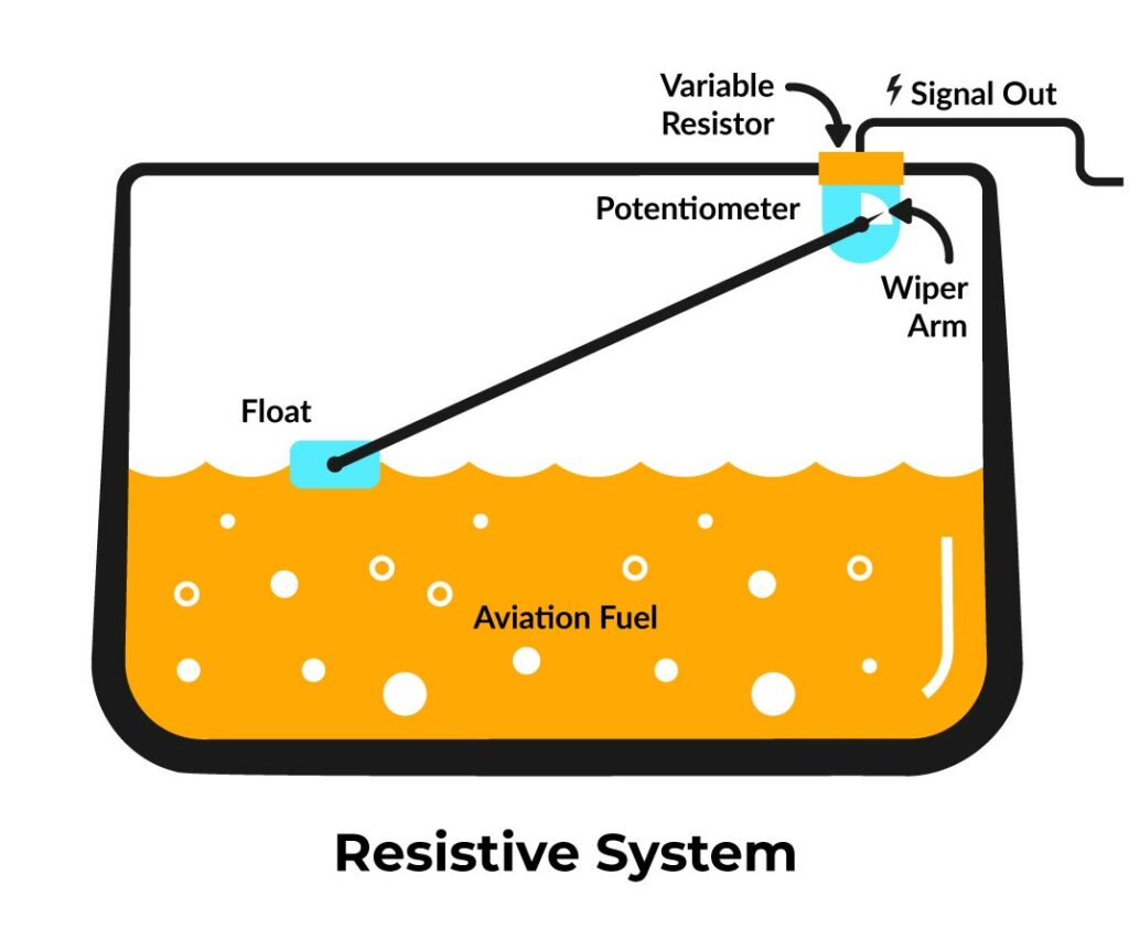
As the fuel level changes in the tank, the float moves accordingly. When the tank is full, the float is at its highest position, and as fuel is consumed, the float drops.
The variable resistor is designed so that its resistance changes as the wiper arm moves along its surface. This resistance variation is due to the varying length of the resistive path the wiper arm contacts.
The variable resistor is connected in an electrical circuit with the fuel gauge. The fuel gauge typically operates as a voltmeter, measuring the voltage drop across the variable resistor. The current flows through the resistor, and the voltage across it changes with the varying resistance.
Advantages of a Resistive System
- Fuel quality doesn’t change the output. The measurement method is typically immersed in fuel. Similar volume measurement.
- No change in output due to fuel temperature or entrained air.
- Float dampens fuel level movement.
- Fuel senders can be mounted in the same OEM location.
Disadvantages of a Resistive System
- Contamination affects potentiometer traces. Accuracy is slowly degraded.
- Fuel motion has considerable effect on potentiometer wiper. Dithering and Morse coding due to motion in and out of plane of the float arm swing.
- Safety hazard present due to electronics and electrical contacts in the fuel tank.
- Water and/or moisture in the fuel tank causes the sender to be grossly degraded.
- Accuracy is poor, as it is reliant on the resistive follower size, the resistance wire, or resistive grid size.
- Float must move wiper against potentiometer reliably. A larger float is needed to overcome corrosion.
- Corrosion highly affects and degrades measurement, restricts motion and deposits corrosion products in the fuel.
- Fuel oscillation provides dithering of output.
- Only offers a resistance output signal.
Capacitive System
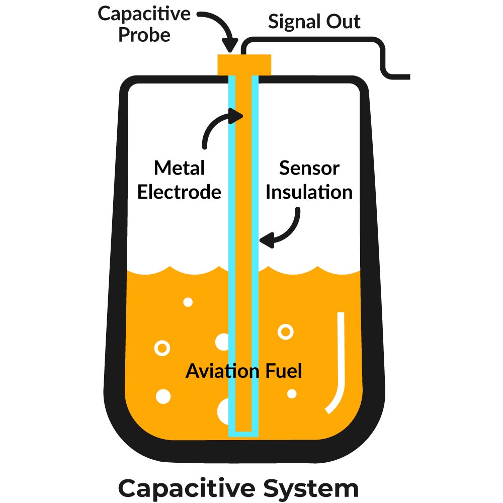
Capacitance is a measure of how much electrical charge can be stored between two conductive plates separated by an insulator (dielectric). The dielectric constant of the fuel changes with the fuel level, leading to changes in capacitance.
The heart of the capacitive system is a capacitive sensor located within the fuel tank. This sensor consists of two plates: one is a conductive plate that is typically positioned on the outside of the fuel tank, and the other is a non-conductive plate attached to a rod that extends into the fuel tank.
The capacitance between the two plates of the capacitive sensor changes as the fuel level changes. When the fuel level is higher, more of the non-conductive plate is immersed in fuel, altering the capacitance.
The changing capacitance is converted into a corresponding electrical signal, often a voltage, using specialized circuitry. This conversion can be achieved through various techniques, such as oscillators that produce a frequency proportional to the capacitance or by measuring the time constant of an RC circuit formed by the sensor plates.
The converted electrical signal is sent to an electronic control unit (ECU) or processing unit for further processing. The ECU interprets the signal, converting the voltage or frequency reading into an actual fuel level measurement.
Advantages of a Capacitive System
- Fuel motion has no effect on sensor.
- Small passages dampen fuel movement.
- The accuracy of simple capacitive systems that have a TSO are 3%. Densitometers, permittivity measurement and temperature compensation are required for better accuracy. Non-TSO capacitive systems are typically less accurate.
- Has physical and electronic damping for fuel oscillation.
Disadvantages of a Capacitive System
- Fuel quality degrades accuracy, due to the differing electrical properties of the fuel.
- Fuel temperature stratification will degrade accuracy. Requires compensation.
- Entrained air will degrade accuracy. Fuel with entrained air has a different and changing electrical property.
- Contamination affects the probe, slowly degrading accuracy.
- Safety hazard present as electronics is in the fuel tank.
- Water or moisture in the tank grossly degrades fuel sender.
- Needs a dedicated position and mount to be compatible with OEM sender locations.
- Corrosion degrades signal output.
- Complexity is high to meet safety and accuracy requirements.
Ultrasonic/Radar/LiDAR
The ultrasonic sensor emits short bursts of ultrasonic waves, which are high-frequency sound waves that are not audible to humans. These waves travel at the speed of sound and propagate through the fuel inside the tank.
The ultrasonic sensor is located within the fuel tank. This sensor emits ultrasonic waves and receives the echoes that bounce back from the fuel surface.
The control module or electronic unit is responsible for processing the ultrasonic signals, calculating the fuel level, and transmitting the information to the fuel gauge.
When the ultrasonic waves encounter the fuel surface, they are partially reflected back towards the sensor. The sensor detects these echoes and measures the time it takes for the waves to travel to the fuel surface and back.
Using the known speed of sound in the fuel (which is affected by factors like temperature and fuel composition), the system calculates the distance between the sensor and the fuel surface based on the time-of-flight of the ultrasonic waves. As the fuel level changes, the distance between the ultrasonic sensor and the fuel surface also changes. The system continuously measures this distance and calculates the corresponding fuel level.
LiDAR and Radar systems operate similarly, in that they employ light waves and sensors to calculate fuel level.
Advantages of an Ultrasonic/Radar/LiDAR System
- Safe system due to no electronics in the fuel tank.
- Mounts in existing fuel sender location.
- Good accuracy when conditions are ideal. Sloshing fuel, fuel temperature stratification and fuel foaming present accuracy issues.
Disadvantages of an Ultrasonic/Radar/LiDAR System
- Subtle changes in fuel composition and quality will change output.
- Fuel temperature affects output as fuel density changes.
- Entrained air affects output as fuel density changes.
- Fuel motion has considerable effect on output.
- Electronic damping only.
- Fuel foam and vapor effect output.
Reed Switch

A series of reed switches are strategically placed along a guide tube or housing inside the fuel tank. These switches are positioned at different levels to correspond with various fuel levels.
These are small, magnetically sensitive switches that consist of two metal contacts encased within a glass envelope. When a magnetic field is applied near the reed switch, the contacts either open or close, depending on the orientation of the field. A magnet is attached to a float that moves up and down with changes in the fuel level.
The float is buoyant and moves up and down with changes in the fuel level inside the tank. As the fuel level changes, the float moves, bringing the attached magnet closer to or farther away from the reed switches.
When the magnet on the float reaches a specific height where a reed switch is located, the magnetic field from the magnet causes the reed switch to either close or open, depending on the design.
The status of each reed switch (open or closed) corresponds to a particular fuel level. The system reads the status of all the reed switches to determine which switches are closed and which are open.
The combination of closed and open reed switches allows the system to determine the fuel level in the tank. Each switch corresponds to a specific segment of the tank’s fuel capacity.

Advantages of a Reed Switch System
- Fuel quality, fuel temperature, entrained air and water in the fuel doesn’t affect output, as only fuel height in the tank or fuel volume is measured in a non-electrical contact manner. The fuel is not a part of the fuel measurement circuit.
- Contamination affects mildly due to self-cleaning design.
- Safe design with no electronics in the fuel tank.
- Float dampens fuel movement.
- Mounts in existing fuel sender locations.
- Unaffected by corrosion.
- Simple design.
Disadvantages of a Reed Switch System
- Poor accuracy and is limited by number of reed switches on the circuit card.
- Fuel motion and oscillation can cause dramatic effects depending on the number and placement of reed switches.
- Only offers resistance output signal.
Magneto-Resistive System

A fuel sender magneto-resistive system is a proven technology used to measure the fuel level in an aircraft fuel tank. It utilizes magneto-resistive sensors that are sensitive to changes in magnetic fields. These sensors detect alterations in the float level and translate them into electrical signals, which can then be used to determine the fuel level.
How It Works
The basic components of a magneto resistive system include specialized sensors and a float assembly. The specialized sensors change their electrical resistance in response to changes in magnetic fields. Magneto-resistive sensors can be based on the Giant Magneto-Resistive (GMR) or Anisotropic Magneto-Resistive (AMR) effects. The float assembly moves up and down with changes in the fuel level.
As the float moves with the changing fuel level, it brings the float assembly closer to or farther away from the magneto-resistive sensors. The magnetic field around the sensors changes because of the magnet’s movement.
The magneto-resistive sensors experience changes in electrical resistance due to the alterations in the magnetic field. These changes are typically detected as variations in voltage or current passing through the sensors.
The electrical signals from the magneto-resistive sensors are sent to an electronic control unit (ECU) or processing unit. The ECU processes the signals to calculate the distance between the sensor and the magnet, which corresponds to the fuel level. This information is then sent to the fuel gauge for display.
Advantages of a Magneto-Resistive System
- Highest accuracy available for fuel quantity measurement. Exceeds 0.75% with no measurable error or hysteresis in TSO testing.
- Fuel quality, fuel temperature and entrained air does not change output as only fuel height in the tank or fuel volume is measured in a non-electrical contact manner. The fuel is not a part of the fuel measurement circuit.
- Contamination affects mildly. This system is self-cleaning due to generous clearances that do not affect system accuracy.
- Fuel motion has no effect on sensor. Out of plane motion has no effect. Dense closed-cell float dampens fuel motion.
- High safety due to no electronics in the fuel tank. Intrinsically safe.
- Float size is minimized, and density is increased which dampens fuel movement.
- Water in the fuel has no effect in output. No electrical contact with the fuel tank contents.
- Mounts in existing fuel sender locations.
- Output signals include frequency, voltage and resistance.
- Float error is minimized as float buoyancy does not need to drive a mechanical interface. Smaller and denser floats are utilized in magnetic field fuel quantity systems.
- Corrosion has no effect on fuel level output.
- Fuel oscillation has no effect. Physical and electronic damping present.
- Simple design (three wires to connect).
Disadvantages of a Magneto-Resistive System
- Can be more expensive due to quality standards.
Comparison of Fuel Sender Technologies
| Sensor Characteristics | Resistive | Capacitive | Ultrasonic / Radar / LiDAR | Reed Switch | Magneto-Resistive |
|---|---|---|---|---|---|
| Fuel Quality | No effect | Accuracy degraded due to differing electrical properties | Fuel composition changes output | No effect | No effect |
| Fuel Temperature | No effect | Fuel temperature stratification will affect accuracy | Fuel density changes output | No effect | No effect |
| Entrained Air | No effect | Fuel with entrained air affects accuracy due to differing electrical properties | Fuel density changes output | No effect | No effect |
| Contamination | Slowly degrades due to potentiometer traces | Slowly degrades | Contamination on target or transmitter changes output | Little effect – self cleaning | Little effect – self cleaning |
| Fuel Motion | Highly affected – dithering and morse coding | No effect | Highly affected | Effect depends on number & quantity of reed switches | No effect – dense float dampens movement |
| Safety | High hazard – electronics in tank | High hazard – electronics in tank | No electronics in fuel tank | No electronics in fuel tank | No electronics in fuel tank |
| Damping | Some damping with float | Good | Electronic damping only | Float dampens movement | Dense float dampens movement |
| Water in Fuel | Highly affected | Highly affected | No effect | No effect | No effect |
| Compatibility | Good – mounts in OEM position | Needs dedicated position and mounting | Good – mounts in OEM position | Good – mounts in OEM position | Good – mounts in OEM position |
| Output Signal | Resistance | Frequency, Voltage | Ratiometric Voltage | Resistance | Frequency, Voltage, Resistance |
| Float Error | Corrosion affects float | Not applicable | Not applicable | Float size determines accuracy | Small, dense float dampens error |
| Corrosion | Highly affected | Degrades output | No effect | No effect | No effect |
| Fuel Oscillation | Highly affected | Good | Fuel foam and vapor affect output | Effect depends on number & quantity of reed switches | No effect |
| Complexity | Simple | Complex | Complex | Simple | Simple |
| Cost | Low | Medium | Medium to High | Low | Medium to High |
| Installation | Medium | Medium | Easy | Medium | Easy |
| Maintenance | Medium to high | Low | Low | Low | Low |
| Accuracy | Poor when corroded | Good | Good when conditions ideal, sloshing fuel, temp and foaming affect accuracy | Accuracy depends on number & quantity of reed switches | Highest accuracy available, exceeds 99% |
*Green is good, Yellow is caution, Red is concerning
Do you need new fuel sending units?
CiES manufactures fuel level senders as a physical bolt-in replacement for Cessna, Beechcraft, Cirrus, Mooney, Piper and many other makes and models. In fact, there are nearly 700 makes and models covered by our FAA STC. Here you can view all covered models. CiES also produces senders for OEM installations for several aircraft manufacturers.

CiES also supports 30+ fuel gauges and instrument panels. These configurations are covered by the same STC. If you require support for an existing gauge (aircraft must have a tank and gauge map), please contact us for details before ordering.
With over 100,000 CiES fuel quantity sender units in the field and 900,000+ hours of trouble-free operation, we are a trusted ally of general aircraft owners and quality aircraft manufacturers. In addition, CiES senders exceed 90,000 hours mean time to failure (MTTF), making our fuel quantity solution one of the most reliable aviation systems in existence.
Would you like to purchase new fuel sending units for your aircraft?
We custom build each order to eliminate installation problems for you and your team. Fill out our order form here.
Share this:
About CiES Inc.
Established in 2012, CiES is now the largest supplier of aviation fuel quantity probes and senders. They are the recognized leader in the design, development, certification, and manufacture of electronic sensor solutions for original equipment manufacturers, as well as direct-to-market consumer products. Through the creative application of cutting-edge technologies, CiES creates complex end-to-end solutions. This is a company that is changing the game in aviation technology and revolutionizing the way we navigate the skies. Aiming at future growth and innovation, CiES is pushing the boundaries of what is possible.
Recent Posts
You might also like...


